Introduction
In most networks, the default gateway is a single point of failure. If that gateway goes down, end hosts lose connectivity even if the rest of the network is fully operational.
First Hop Redundancy Protocols (FHRPs) solve this problem by providing gateway high availability. They allow multiple routers to present a single virtual default gateway to hosts, ensuring seamless failover if one device or path fails.
In this lab, we’ll take a hands-on approach to FHRPs by configuring and testing:
- HSRP for active/standby redundancy and VLAN-based load balancing
- VRRP as an open-standard alternative with built-in preemption
- GLBP for true active/active load balancing using virtual MAC addresses
The focus isn’t just configuration we’ll validate real world behavior like failover, tracking, and upstream failure detection to ensure redundancy actually works in practice.
Topology & Base Configuration
All routers have a loopback address applied that matches their router name.
For Example R1 = 1.1.1.1/32
Interface IPs follow a consistent pattern: x.x.x.(Device Number). For example, on subnet 10.0.0.0/24 between R2 and R8, R2 uses 10.0.0.2/24 and R8 uses 10.0.0.8/24.
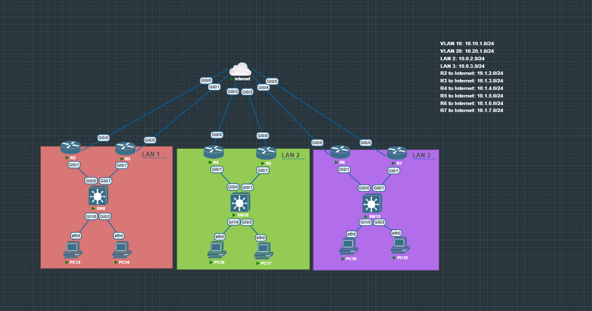
All Subnets, ROAS, Vlans, and IGP Routing has been pre-configured.
HSRP Configuration with Load Balancing
In this lab, HSRP is used not just for redundancy, but also for basic load balancing by splitting traffic across multiple VLANs.
The idea is simple:
- Each VLAN has its own HSRP group
- A different router is Active for each VLAN
- This allows both routers to actively forward traffic instead of one sitting idle
Configuration Overview
- Configure HSRP on both routers in LAN 1
- Set:
- Virtual IP (default gateway for hosts in both VLANs)
- Separate HSRP groups per VLAN
- VLAN 10 → R2 Active
- VLAN 20 → R3 Active
- Preemption (with delay to prevent flapping)
- Priority to control Active router election
R2 Configuration
interface g0/1.10
standby 10 ip 10.10.1.1
standby 10 priority 101
standby 10 preempt delay minimum 10

interface g0/1.20
standby 20 ip 10.20.1.1
standby 20 preempt delay minimum 10
R3 Configuration
interface g0/1.10
standby 10 ip 10.10.1.1
standby 10 preempt delay minimum 10

interface g0/1.20
standby 20 ip 10.20.1.1
standby 20 priority 101
standby 20 preempt delay minimum 10
What This Achieves
- VLAN 10 traffic is primarily handled by R2
- VLAN 20 traffic is primarily handled by R3
- Both routers are actively forwarding traffic → better resource utilization
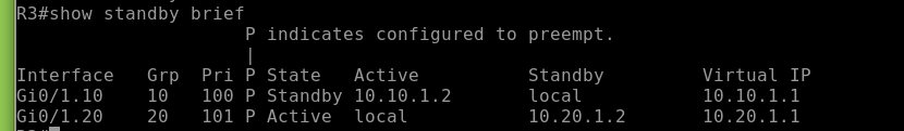
Verification
Check HSRP status on both routers:
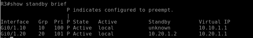
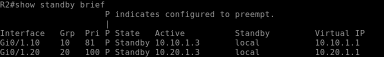
show standby brief
You should see:
-
R2 as Active for VLAN 10 (Group 10)
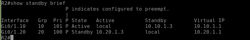
-
R3 as Active for VLAN 20 (Group 20)
Real-World Insight
This is the most common way to achieve load balancing with HSRP in production.
Instead of relying on more complex protocols like GLBP, networks often use multiple HSRP groups + VLAN design to keep things simple and predictable.
Failover Testing (HSRP)
Validate that HSRP failover works as expected by simulating a failure.
Test Scenario
Shut down the Active router interface:
interface g0/1.10
shutdown
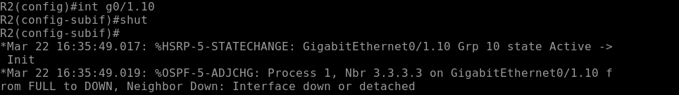
Verify
- Standby router becomes Active
- Virtual IP and MAC move over
- Hosts maintain connectivity (minimal packet loss)
Check:
show standby brief
Test Preemption
Bring the interface back up:
interface g0/1.10
no shutdown
- Higher priority router should reclaim Active role (after delay)
Interface Tracking
Interface tracking allows HSRP to fail over when a critical link (like a WAN uplink) goes down even if the router itself is still up.
Configuration Example R2
track 1 interface g0/0 line-protocol
interface g0/1.10
standby 10 track 1 decrement 20
- Tracks interface g0/0 (WAN link)
- Decrements HSRP priority by 20 if it goes down
Test Scenario
Simulate WAN failure:
interface g0/0
shutdown
Verify
- HSRP priority is reduced
- Standby router takes over as Active
- Traffic shifts to the backup path
Check:
show standby brief
What This Solves
Prevents black hole routing where:
- Router is still up
- But interface is down
Real-World Insight
Without tracking, HSRP won’t fail over during upstream failures only full device/interface failures. Tracking is what makes redundancy actually work in production.
IP SLA Tracking
IP SLA tracking allows HSRP to fail over based on upstream reachability, not just interface state.
Configuration Example
ip sla 1
icmp-echo 8.8.8.8
frequency 5
ip sla schedule 1 life forever start-time now

track 2 ip sla 1 reachability

interface g0/1.10
standby 10 track 2 decrement 20
- Sends ICMP probes to verify upstream connectivity
- Links SLA to a tracking object
- Decrements HSRP priority if reachability fails
Test Scenario
Simulate upstream failure:
- Block ICMP or remove upstream route
Verify
- Track object goes down
- HSRP priority decreases
- Standby router becomes Active
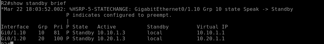
Check:
show track
show standby brief
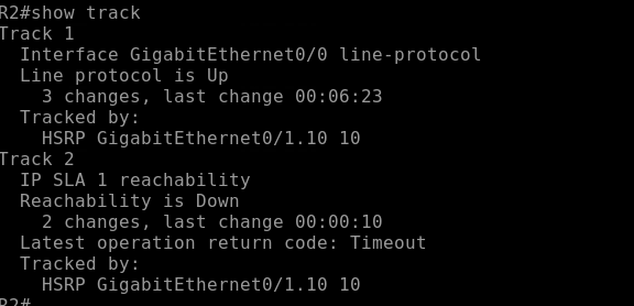
What This Solves
Detects failures beyond the local router, preventing traffic from being sent to a dead upstream path.
Real-World Insight
Interface tracking only sees link state. IP SLA sees actual reachability this is what you use in real networks to avoid silent failures.
VRRP Configuration
Configure VRRP on both routers 4 & 5 (no VLANs, single subnet).
Configuration Example
R4 (higher priority → Master):
interface g0/1
vrrp 10 ip 10.0.2.1
vrrp 10 priority 110
R5:
interface g0/1
vrrp 10 ip 10.0.2.1
Verify
- R4 = Master, R5 = Backup
- Virtual IP is reachable as default gateway
Check:
show vrrp brief


Preemption Behavior
- Enabled by default in VRRP
- Higher priority router will automatically take back Master role when it returns
GLBP Configuration
Configure GLBP on both routers to provide gateway redundancy + load balancing.
Configuration Example
R6:
interface g0/1
glbp 10 ip 10.0.3.1
glbp 10 priority 110
glbp 10 preempt
R7:
interface g0/1
glbp 10 ip 10.0.3.1
glbp 10 preempt
Verify
- One router = AVG (Active Virtual Gateway)
- Both routers can be AVFs (Active Virtual Forwarders)
- Multiple virtual MAC addresses are assigned
Check:
show glbp brief
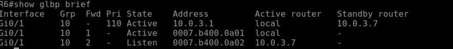
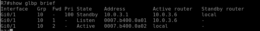
This command gives you a quick overview of:
- GLBP group number
- Virtual IP address
- Role of each router (AVG or AVF)
- Forwarder state
How to Identify Roles
-
AVG (Active Virtual Gateway)
- The router responsible for answering ARP requests for the virtual IP
- Assigns different virtual MAC addresses to hosts
- Only one AVG per group
-
AVF (Active Virtual Forwarder)
- Routers that actually forward traffic for a given virtual MAC
- There can be multiple AVFs (this is what enables load balancing)
What to Look For in Output
- One router listed as Active → this is your AVG
- Multiple forwarders in Active state → these are your AVFs
- Each forwarder has a unique virtual MAC address
Test Load Balancing
- Ping or generate traffic from multiple hosts
- Each host should receive a different virtual MAC
- Traffic is distributed across both routers
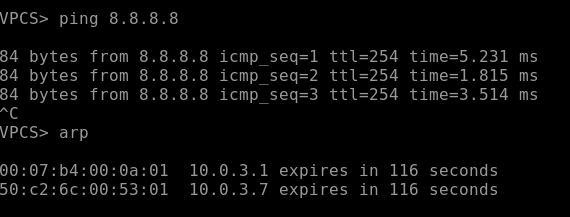
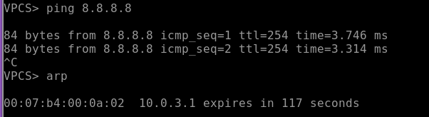
Understanding GLBP VMACs
GLBP assigns multiple virtual MAC addresses (VMACs) to a single virtual IP address. This is what enables load balancing.
- Each AVF (Active Virtual Forwarder) owns a unique VMAC
- The AVG responds to ARP requests and hands out different VMACs to different hosts
- Hosts all use the same default gateway IP, but forward traffic to different MAC addresses
Real-World Insight
GLBP gives you active/active gateway usage, unlike HSRP/VRRP which are active/standby by default
Conclusion
First Hop Redundancy Protocols (FHRPs) are a critical part of building resilient networks, ensuring that the default gateway is always available even during failures.
In this lab, you configured and tested:
- HSRP for active/standby redundancy with load balancing via multiple groups
- VRRP as an open-standard alternative with built-in preemption
- GLBP for true active/active load balancing using virtual MAC addresses
You also validated real-world behaviors like:
- Failover during interface and upstream failures
- Priority-based elections and preemption
- Interface tracking and IP SLA for intelligent failover
- Load balancing using GLBP VMAC distribution